Bose 3.2.1 GSX Specifications Page 45
- Page / 68
- Table of contents
- BOOKMARKS
- CONTENTS 1
- SAFETY INFORMATION 2
- WARRANTY 2
- PRODUCT DESCRIPTION 3
- ACCESSORIES 3
- SPECIFICATIONS 4
- PART LIST NOTES 8
- DEVICE HANDLING 8
- FREQUENTLY ORDERED ITEMS 9
- PACKAGING PART LIST 10
- Figure 1. 3 11
- Figure 3. 3 14
- MAIN PART LIST 15
- Figure 5. Standard 3 16
- ELECTRICAL PART LIST 18
- Capacitors (continued) 26
- Console Main PCB Assembly 26
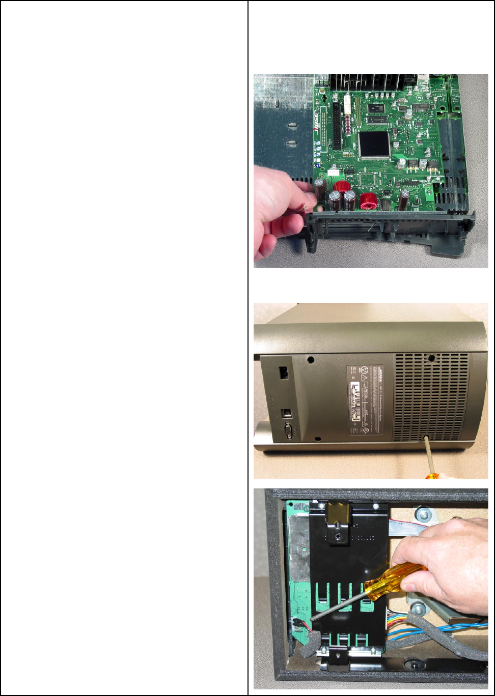
- DISASSEMBLY PROCEDURES 42
- TEST PROCEDURES 48
- APPENDIX 62
- DVD Lock options 63
- DVD Lock Bypass 64
- DVD Lock options (continued): 64
- GLOSSARY OF TERMS 65
- Service Manual 67
- Bose Corporation 68
- The Mountain 68
© 2020, manymanuals.com. All rights reserved. | 1.522 s |
 Manymanuals.com
 Manymanuals.de
 Manymanuals.fr
 Manymanuals.it
 Manymanuals.pl
 Manymanuals.cz
 Manymanuals.es
 Manymanuals-pt.com
Comments to this Manuals