Bose 1600-VI Specifications Page 14
- Page / 32
- Table of contents
- BOOKMARKS
- Stereo Power Amplifier 1
- 1.0 Safety Information 2
- Atención 3
- Avvertenza 3
- Waarschuwing 4
- Where to find 5
- 2.1 Unpacking the amplifier 6
- 2.0 Before You Begin 6
- 4.6 Input wiring 8
- Figure 1 8
- Figure 2 8
- Figure 3 9
- Figure 4 9
- Figure 5 10
- Figure 6 10
- 4.0 Installation 10
- 4.7 Input sensitivity 11
- Figure 7 11
- 4.8 Output wiring 12
- Figure 8 13
- 4.9 Clipping eliminator 13
- 5.2.1 Standard input module 14
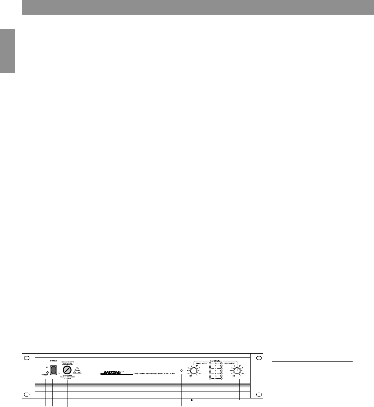
- 5.0 Operation 15
- 5.4 Rear panel 16
- Figure 10 16
- Figure 11 16
- Figure 12 18
- Figure 13 18
- Problems/solutions 19
- Features of the Bose 20
- Model 1800-VI and 1600-VI 20
- Warranty period 21
- Specifications for Bose 22
- 9.0 Specifications 23
- Descripción general 24
- Configuración del sistema 24
- Información técnica 24
- Appendix 24
- Bose Corporation 31
- ©2000 Bose Corporation 32
- The Mountain, Framingham 32
- MA 01701-9168 USA 32
- 198352 AM Rev.02 JN10421 32
- PC023298 32
Related products and manuals for Audio amplifiers Bose 1600-VI
 (20 pages)
 (32 pages)
 (20 pages)
 (20 pages)
(60 pages)
(2 pages)
(20 pages)
(60 pages)
(2 pages)
 (11 pages) (8 pages)
© 2020, manymanuals.com. All rights reserved. | 1.366 s |
 Manymanuals.com
 Manymanuals.de
 Manymanuals.fr
 Manymanuals.it
 Manymanuals.pl
 Manymanuals.cz
 Manymanuals.es
 Manymanuals-pt.com
Comments to this Manuals