Bose ControlSpace CC-16 Installation Guide Page 7
- Page / 17
- Table of contents
- BOOKMARKS
- ControlSpace 1
- English User Guide Page 3 2
- Important Safety Instructions 3
- Safety Information 4
- IntroductIon 5
- Available Accessories 6
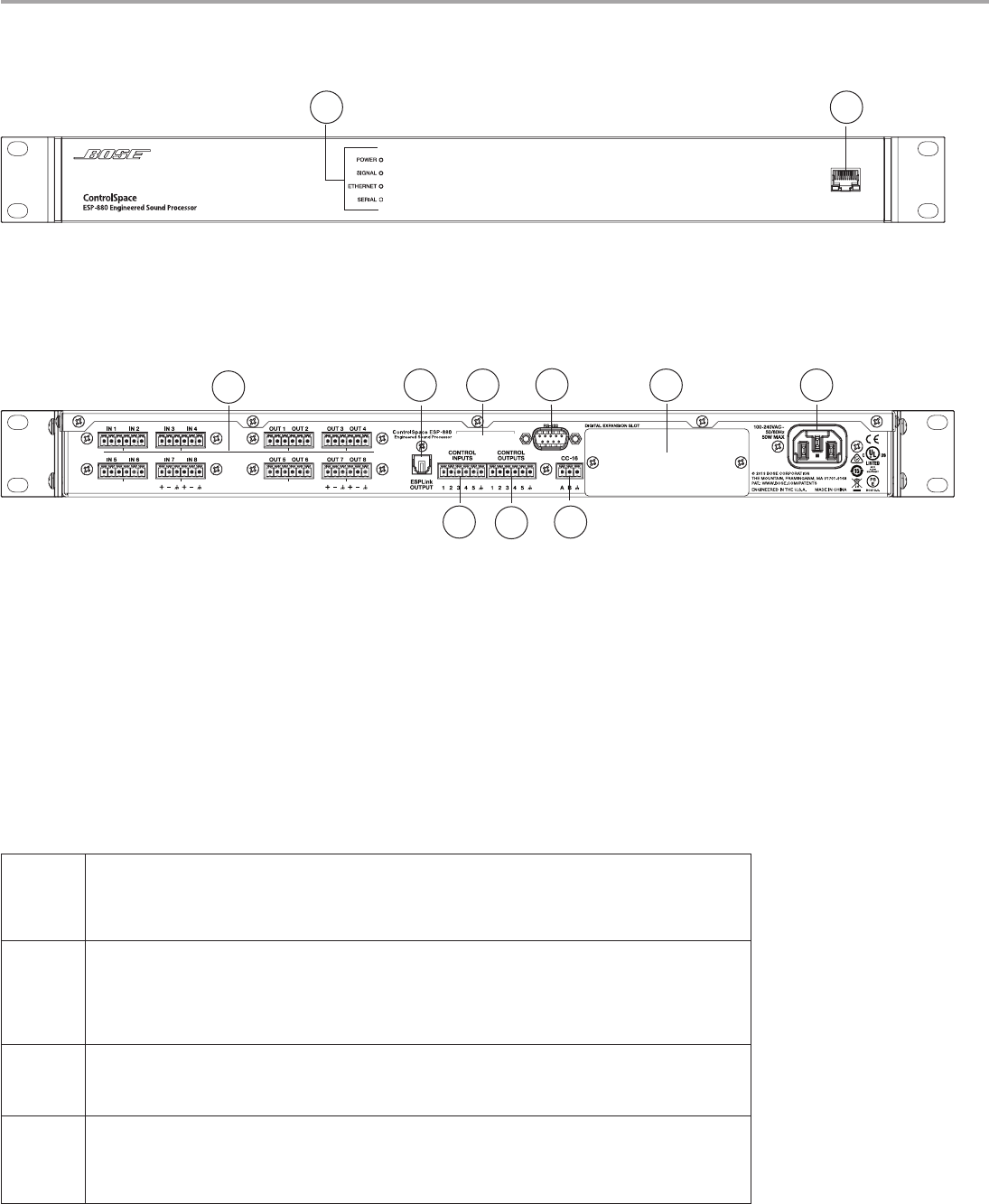
- Product overvIew 7
- Hardware InstallatIon 8
- 5. Analog Audio Connections 9
- English User Guide Page 17 10
- 7. Connect GPIO devices 11
- 8. Network Connections 12
- 9. Power Cord Connection 12
- MaIntenance oPeratIons 13
- Appendix 14
- Technical Specifications 15
- Additional Resources 16
- AM372643 Rev. 00 17
© 2020, manymanuals.com. All rights reserved. | 0.728 s |
 Manymanuals.com
 Manymanuals.de
 Manymanuals.fr
 Manymanuals.it
 Manymanuals.pl
 Manymanuals.cz
 Manymanuals.es
 Manymanuals-pt.com
Comments to this Manuals