7
YOUR SL2 WIRELESS SURROUND LINK
English Deutsch FrançaisDansk Español Italiano SvenskaNederlands
Connecting the SL2 receiver
Use the supplied 20-ft (6.2-m) cables to connect the speakers to the SL2 receiver. Or, you may
prefer to use the longer surround speaker cables that came with your speakers.
Note: To use the SL2 supplied cables with Jewel Cube
®
speakers, first attach a Jewel Cube
adapter to each cable as described in “To adapt the surround speaker cable for Jewel Cube
®
speakers” on page 8.
To make the receiver connections
Using the supplied cables, follow the steps below:
1. Insert the RCA connectors into the jacks on the back of the SL2 receiver (Figure 5).
• Connect the purple one marked RR to the purple jack labeled RR.
• Connect the green one marked LR to the green jack labeled LR.
2. Connect the wire ends of the cable to your surround speakers.
• Insert the wire marked RR into the terminal on the speaker that is placed
on the right.
• Insert the wire marked LR into the terminal on the speaker that is placed
on the left.
For details on how to set up and make connections to your surround speakers, refer to
the owner’s guide provided with them.
3. Connect the cable end of the receiver power pack to the small jack labeled DC Power on
the back of the receiver.
4. Connect the power cord to the receiver power pack and insert the power cord plug into a
nearby AC (mains) outlet.
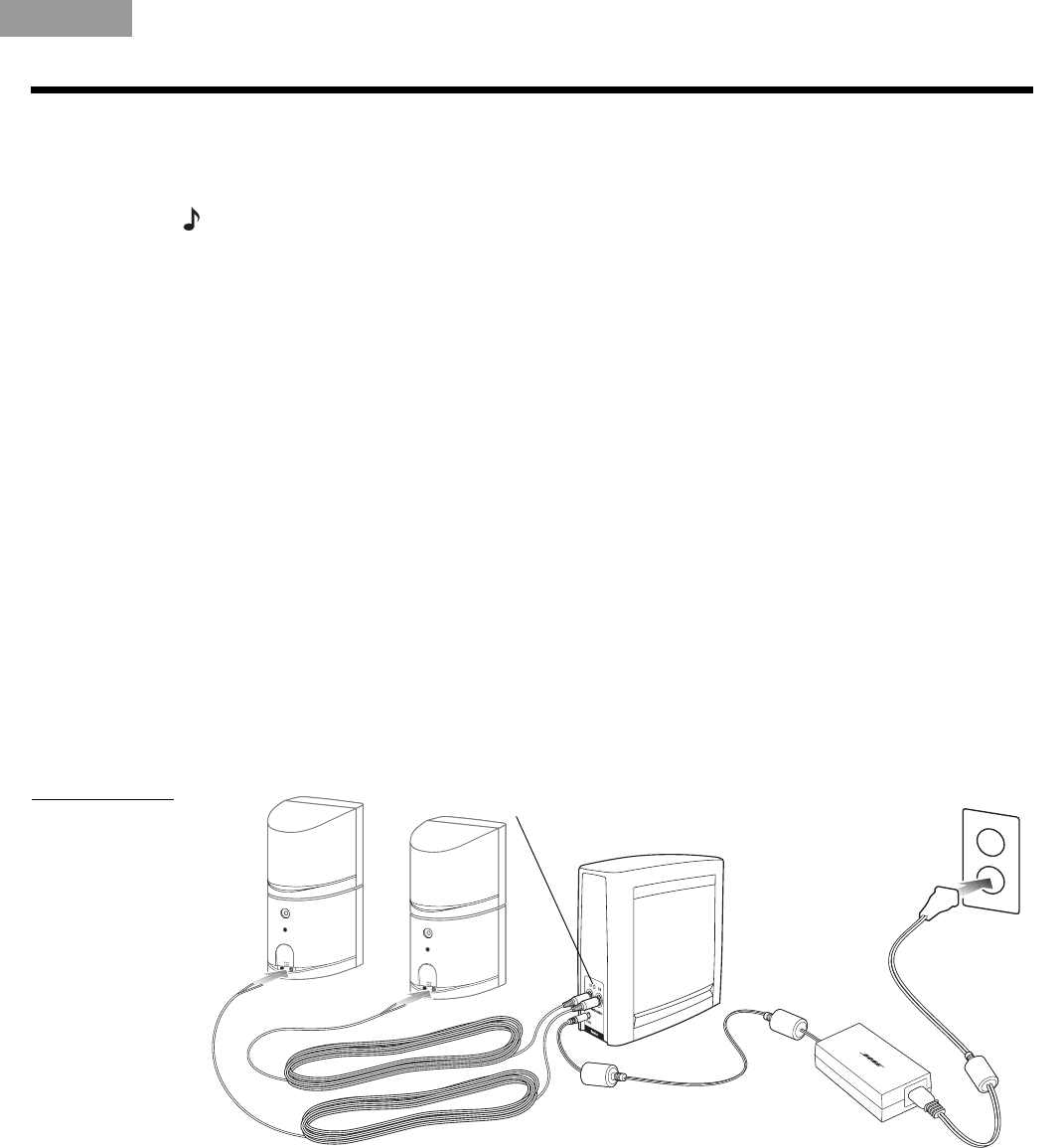
Figure 5
SL2 receiver
connection to
speakers
Surround
speaker cables
SL2 receiver
urroun
soun
spea
ers
Receiver
power pack
Status LED
AC power
outlet
Receiver
power cord
When this power supply is plugged in, the Status LED on the back of the SL2 receiver blinks
green until it links to the transmitter. If the transmitter has no audio signal to communicate to
the receiver, the LEDs on both units turn orange. When the two are communicating with each
other, their LEDs turn a solid green.
For an explanation of the other LED colors, refer to “What the Status LEDs indicate” on
page 8.
00_CatapultOG.book Page 7 Thursday, October 26, 2006 4:07 PM
 (17 pages)


 (32 pages)
 Manymanuals.com
 Manymanuals.de
 Manymanuals.fr
 Manymanuals.it
 Manymanuals.pl
 Manymanuals.cz
 Manymanuals.es
 Manymanuals-pt.com
Comments to this Manuals