3
3
pro.Bose.com
O
O
F
F
8
8
FreeSpace
®
DXA 2120
Digital Mixer/Amplifier
TECHNICAL DATA SHEET
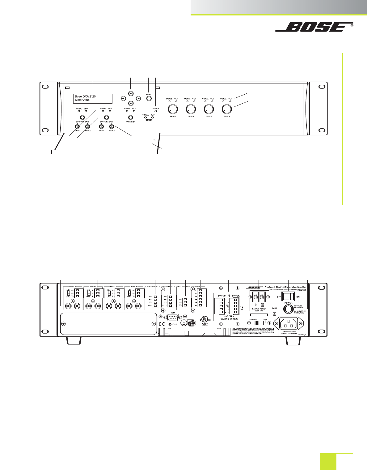
Front and Rear Panel Diagrams
1 LCD panel – Displays menu selections for
configuring and viewing system settings.
2 Directional buttons – Navigates system menus
and setting options shown on the LCD.
3 SELECT button – Confirms selections and
settings in the system menus.
4 POWER LED – Blue light indicates the system
is on. No light when unit is off.
5 SIGNAL and CLIP LEDs – Shows signal states for
OUTPUT 1, OUTPUT 2, PAGE and DIRECT.
Signal Unlit = No signal Clip Unlit = No clipping
Signal Green = Signal present Clip Red = Clipping
6 GAIN knobs – Adjusts gain for OUTPUT 1,
OUTPUT 2 and PAGE.
7 BASS and TREBLE knobs – Adjusts tonal
balance for OUTPUT 1 and OUTPUT 2.
8 Enclosure door – Conceals system controls.
9 SIGNAL and CLIP LEDs – Shows signal states for
Inputs 1 – 4.
Signal Unlit = No signal Clip Unlit = No clipping
Signal Green = Signal present Clip Red = Clipping
10 Gain knobs – Adjusts gain for INPUT 1 – INPUT 4.
1 LINE INPUTS – Two unbalanced RCA audio jacks
per input (summed to mono).
2 MIC/LINE INPUTS – Balanced Euroblock input
jacks. One per input.
3 MIC/LINE switch – Adjusts for the proper
signal level being used with the four Euroblock
input connectors. (Mic connections require use
of the Euroblock input jacks.)
4 DIRECT INPUT – Balanced override input jack.
5 PAGE INPUT – Balanced audio input jack.
6 AUX OUTPUT – Fixed line-level signal output for
other amplified equipment.
7 OUTPUTS 1 and 2 – Speaker connections for two
powered outputs (70V, 100V or 4-ohm operation).
8 REMOTE – Input jack for volume-only control and
volume control with A/B select user interfaces.
9 BACKUP POWER – For connection to backup
power source.
10 POWER OFF/ON – AC power switch.
11 FUSE – T6.3AL/250V (100V and 120V) or
T3.15AL/250V (220-240V).
12 AC mains line cord jack – AC line voltage input.
13 120V/220-240V switch – Switches between 120V
and 220-240V AC input voltage. This switch is
not provided on 100V AC input voltage models.
14 COM – RS-232 serial port is reserved for
system updates.
1 2 3 4
9
10
8
7
6
5
1
3 2 4 5 6 8 7 9 10 11
14 13 12
 (30 pages)
 Manymanuals.com
 Manymanuals.de
 Manymanuals.fr
 Manymanuals.it
 Manymanuals.pl
 Manymanuals.cz
 Manymanuals.es
 Manymanuals-pt.com
Comments to this Manuals