Bose 2150 Specifications
Browse online or download Specifications for Audio amplifiers Bose 2150. Bose 2150 Specifications User Manual
- Page / 39
- Table of contents
- TROUBLESHOOTING
- BOOKMARKS
- M 2150 1
- Important Safety Instructions 2
- Where to find 3
- 2.1 Unpacking the amplifier 4
- 3.1 Using the Bose 5
- Model 2150 commercial power 5
- 3.2 General precautions 5
- 3.4 Thermal considerations 6
- 3.5 AC power considerations 6
- 4.1 Front Panel 7
- 4.1 Front Panel (Cont.) 8
- 4.2 Rear Panel 10
- 4.2 Rear panel (cont.) 11
- 4.2 Rear panel (cont.) 12
- Figure 7 14
- 4.0 Operation 14
- Figure 6 14
- Figure 8 15
- Figure 9 15
- 5.0 Installation 19
- Figure 13 19
- Figure 14 19
- Figure 15 19
- Figure 16 19
- 5.1 Installing Bose 20
- EQ Cards (cont.) 20
- 5.2 Input wiring 23
- Figure 28 24
- 5.2.2 Unbalanced operation 24
- Figure 27 24
- Figure 29 25
- Figure 30 26
- 5.3 Output wiring 27
- 5.3 Output wiring (cont.) 28
- 5.3.5 Stereo operation 29
- Figure 33 29
- 5.3.6 Bridged mono operation 30
- Figure 35 30
- Figure 34 30
- 5.3.7 Parallel mono 31
- 5.0 Installation 31
- Troubleshooting 32
- Warranty period 33
- 50 Commercial Power 34
- Amplifier 34
- Amplifier (cont.) 35
- Bose Corporation 38
- ©2002 Bose Corporation 39
- The Mountain, Framingham 39
- MA 01701-9168 USA 39
- 264080 AM Rev.00 JN20950 39
Summary of Contents
Bose® Model 2150 Commercial Power AmplifierInstaller’s GuideGuía de instalaciónNotice d’installationClip-12dB-20dBReadySignalProtectThermal-6dBClip-12
10English4.2 Rear PanelInput Modules1. Standard input moduleThrough the use of the Bose® input module (the standard module provided with the ampli-fi
11English4.0 Operation4.2 Rear panel (cont.)3. EQ out connectorsA 1⁄4" TRS output connector provides access to an equalized line level output s
12English4.0 Operation4.2 Rear panel (cont.)5. Speaker outputsBarrier block speaker outputs on each channel accommodate independent connections for4Ω
13English4.2 Rear panel (cont.)FX Loop in/outEngages or bypasses the FX loop. ON (on) allows signals to pass through the FX loop. OFF(off) closes the
14English8. AC Power sequence connectorA three-pin Euro style terminal and mating connector are supplied with each amplifier toallow the amplifier to
15English8. AC power sequence connector (cont.)To remotely begin the sequencing function, close the circuit and supply the DC voltage tothe RCV receiv
16English8. AC power sequence connector (cont.)When mounting the amplifiers in a common rack, you should verify if the amplifiers’ chassisare sharing
17English4.2 Rear panel (cont.)9. REMOTE LEVEL (remote level) controlUse a 1k to 10k potentiometer, preferably with a reverse log taper. Identify the
18EnglishCOM4.2 Rear panel (cont.)10. PowerInsert the power cord into a properly configured A/C power mains.J20018292SENDRECVSEND RECV120VAC, 4.6A max
19English5.1 Installing Bose® EQ CardsIf your Bose loudspeakers require active equalization, follow these steps to install them inthe Model 2150:1. Tu
2EnglishWarningTo reduce the risk of fire or electric shock, do not expose the unit to rain or moisture.CAUTIONRISK OF ELECTRICAL SHOCKDO NOT OPENCAUT
20English5.1 Installing Bose® EQ Cards (cont.)If your Bose loudspeakers require active equalization, follow these steps to install them inthe Model 21
21English5.1 Installing Bose® EQ Cards (cont.)If your Bose loudspeakers require active equalization, follow these steps to install them inthe Model 21
22English5.1 Installing Bose® EQ Cards (cont.)If your Bose loudspeakers require active equalization, follow these steps to install them inthe Model 21
23English5.2 Input wiringYou can use 1⁄4" phone jacks, XLR connectors, or quick connect terminal blockconnectors for the input signal with eithe
24EnglishFigure 281⁄4" phone jack unbalancedinput connection5.0 Installation5.2.1 Balanced operation (cont.)For the quick connect terminal bloc
25English5.2.2 Unbalanced operation (cont.)For the XLR connector, pin 2 carries the + (hot, non-inverting) side of the signal, and pin 1 isground. To
26EnglishFigure 30Quick connect terminal blockunbalanced input connection5.0 Installation5.2.2 Unbalanced operation (cont.)For the quick connect term
27English5.0 Installation5.3 Output wiringThe Model 2150 speaker outputs on the amplifiers can accommodate wire from 20 gaugeup to 12. We recommend
28English5.3 Output wiring (cont.)5.3.3 Stereo/Mono switchThis switch selects between NORMAL STEREO (normal stereo), DUAL MONO (dual mono),or BRIDGED
29English5.3.5 Stereo operationThe STEREO/MONO switch is located behind slot #2 of the standard input module (seeFigure 31). For stereo operation move
3EnglishContentsWhere to find...1.0 Safety Information ...
30English5.3.6 Bridged mono operationThe STEREO/MONO switch is located behind slot #2 of the standard input module (seeFigure 31). For bridged mono o
31English5.3.7 Parallel monoParallel mono operation is useful when running sustained high levels in a single load orwhen driving a low impedance load
32EnglishProblem Cause or SolutionNo sound, no power • Check amplifier. Power off, then turn on.• Linecord disconnected.• Poor fit between the plug an
33EnglishAppendix A: Features, Warranty, ServiceWarranty periodBose® warrants the Model 2150 commercial power amplifier with a five-year, transferabl
34EnglishAppendix B: SpecificationsSpecifications for Bose® Model 2150 Commercial PowerAmplifierPower OutputContinuous average output power, both ch
35EnglishAppendix B: SpecificationsSpecifications for Bose® Model 2150 Commercial PowerAmplifier (cont.)IM distortion0.2%THD<0.5% rated power, &l
36English
Bose CorporationBose Corporation
Bose CorporationBose Corporation
©2002 Bose Corporation,The Mountain, FraminghamMA 01701-9168 USA264080 AM Rev.00 JN20950
4EnglishThank you for purchasing a new Bose® commercial power amplifier. It is backed by state-of-the-art engineering and manufacturing techniques to
5English3.1 Using the Bose® Model 2150 commercial poweramplifierOnce you have installed and wired the amplifier, follow these tips to get the most fr
6English3.4 Thermal considerationsWhen the amplifier is used freestanding, no thermal considerations are necessary otherthan keeping sufficient ventil
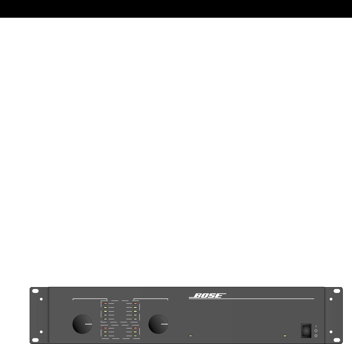
7English4.0 Operation4.1 Front Panel1. Level controlsIndependent level controls are provided for Channel 1 and Channel 2. When each levelcontrol is
8English4.1 Front Panel (Cont.)2. Level indicatorsThe level indicators (see Figure 2) for each channel reflect the gain of each output stage. Thefol
9English4.0 Operation4.1 Front Panel (Cont.)3. Status indicators (cont.)PROTECT – A yellow light indicates if there is:1. An over or under voltage
Related products and manuals for Audio amplifiers Bose 2150

 (32 pages)
 (20 pages)
(32 pages)
(20 pages)
(32 pages)
 (20 pages)
 (20 pages)
(60 pages)
(2 pages)
(20 pages)
(60 pages)
(2 pages)
© 2020, manymanuals.com. All rights reserved. | 0.479 s |
 Manymanuals.com
 Manymanuals.de
 Manymanuals.fr
 Manymanuals.it
 Manymanuals.pl
 Manymanuals.cz
 Manymanuals.es
 Manymanuals-pt.com
Comments to this Manuals